Industrial Control Panel Design
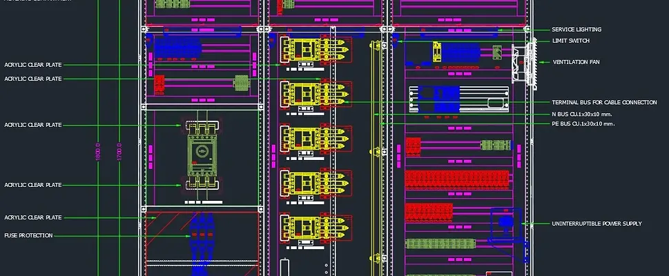
Practical electrical control panel design that supports reliable manufacture, installation, operation and maintenance.
Stratos Control Systems designs industrial control panels for machinery, production lines, process systems and wider automation applications.
From the initial system requirements to the final electrical drawings, every design decision is made with the completed panel, connected equipment and long-term operation in mind.
Our control panel designers combine electrical engineering, PLC automation and practical panel-building experience to produce designs that are clear, compliant, maintainable and ready for manufacture.
Control Panel Design Built Around Your Application
No two industrial control panels have exactly the same requirements.
The panel design must account for the equipment being controlled, operational environment, available power supply, automation architecture and the people who will operate and maintain the system.
Stratos provides control panel design for:
-
New machinery and production equipment
-
Process control systems
-
PLC and automation projects
-
Machine control upgrades
-
Obsolete control panel replacement
-
Existing panel refurbishment
-
SCADA and HMI systems
-
Motor control applications
-
Remote I/O panels
-
Safety-related control systems
-
Building and facilities control systems
-
Production-line modifications
The design can be provided as a standalone engineering service or as part of a complete control panel design, manufacture, programming, testing and commissioning project.
Our Control Panel Design Process
A reliable control panel starts with a structured design process.
Before drawings are produced, we work to understand how the system needs to operate, what equipment it will control and how it will integrate with the wider installation.
Understanding the Requirements
The design process begins by reviewing the operational and technical requirements.
This may include:
-
Functional design specifications
-
Process descriptions
-
Equipment lists
-
Motor and drive requirements
-
Instrument schedules
-
Existing electrical drawings
-
PLC and control-system requirements
-
Safety functions
-
Site standards
-
Customer specifications
-
Environmental conditions
-
Available power supplies
-
Communication-network requirements
Where documentation is incomplete, our engineers can help identify the information required to move the project forward.
Developing the Control-System Architecture
The control-system architecture defines how the panel, PLC, field equipment and connected systems will work together.
This can include:
-
PLC selection
-
Local and remote I/O
-
HMI integration
-
SCADA connectivity
-
Variable-speed drives
-
Motor starters
-
Safety relays or safety PLCs
-
Industrial communication networks
-
Power distribution
-
Field instrumentation
-
Remote control panels
-
Interfaces with existing equipment
The architecture provides the foundation for the electrical schematics, panel layout and I/O schedule.
Component Selection
Components are selected according to the application, electrical load, control requirements and customer preferences.
This may include:
-
PLC hardware
-
Input and output modules
-
Power supplies
-
Circuit protection
-
Contactors and relays
-
Motor protection devices
-
Variable-speed drives
-
Safety devices
-
Network switches
-
Terminal blocks
-
Control transformers
-
Cooling and ventilation equipment
-
HMIs and operator controls
We also consider product availability, manufacturer support, maintainability and future replacement requirements.
Electrical Schematic Design
Once the system architecture and components are agreed, detailed electrical schematics are developed.
These drawings define how the equipment will be powered, connected and controlled.
The electrical drawing package may include:
-
Incoming power arrangements
-
Power distribution
-
Control circuits
-
PLC input and output connections
-
Motor-control circuits
-
Safety circuits
-
Drive connections
-
Instrumentation wiring
-
Terminal plans
-
Field connections
-
Network connections
-
Cable references
-
Component schedules
-
Drawing indexes
The schematics form a central reference for panel manufacture, PLC programming, testing, installation and future maintenance.
Control Panel Layout
The internal panel layout determines where each component will be installed within the enclosure.
The layout must provide enough space for safe assembly, wiring, heat dissipation, maintenance and future modifications.
Our designers consider:
-
Enclosure dimensions
-
Component clearances
-
Cable trunking
-
DIN rail positioning
-
Power and control segregation
-
Heat-producing components
-
Airflow
-
Door-mounted devices
-
Terminal accessibility
-
PLC and I/O access
-
Cable-entry points
-
Future expansion
-
Safe maintenance access
The proposed layout is reviewed before the panel enters manufacture.
Design Review
Before the design is released, the drawings and supporting schedules are reviewed for accuracy and consistency.
The review may include checking:
-
Component ratings
-
Electrical loads
-
Cable sizes
-
Protection devices
-
Terminal references
-
Wire numbers
-
PLC addresses
-
Drawing cross-references
-
Panel dimensions
-
Heat dissipation
-
Safety circuits
-
Customer requirements
-
Spare capacity
Design reviews help identify potential problems before they become panel-building or commissioning issues.
Manufacture and Testing Support
Where Stratos manufactures the control panel, our design and panel-building teams work together throughout the project.
Questions raised during manufacture can be resolved directly by the engineers responsible for the drawings.
The design documentation is also used to support:
-
Panel wiring
-
Component identification
-
Inspection
-
Electrical testing
-
PLC software development
-
Factory acceptance testing
-
Installation
-
Commissioning
Any approved changes made during the project can be incorporated into the final drawings.
As-Built Documentation
Once the panel has been manufactured, installed and commissioned, the drawings can be updated to reflect the completed system.
As-built documentation provides a more dependable reference for maintenance teams, future engineers and automation contractors.
EPLAN Control Panel Design
Stratos uses EPLAN to create structured electrical schematics and manufacturing documentation for industrial control panels.
EPLAN supports intelligent electrical design by linking components, connections, devices and drawing references throughout the project.
Our EPLAN control panel design capability can include:
-
Electrical schematics
-
Panel layouts
-
Terminal plans
-
Cable schedules
-
PLC input and output documentation
-
Component reports
-
Device tagging
-
Wire numbering
-
Parts lists
-
Manufacturing documentation
-
Revision-controlled drawing packages
EPLAN can be particularly valuable for complex projects, standardised machine designs and organisations that already use EPLAN as part of their engineering process.
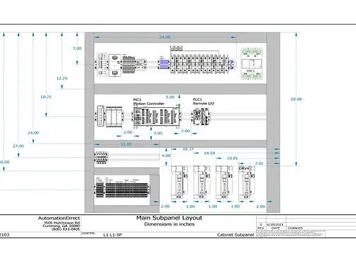
AutoCAD Electrical Control Panel Design
AutoCAD Electrical is used to create and manage electrical drawings for industrial control systems and control panels.
It provides specialist tools for electrical schematics, component identification, wire numbering and drawing cross-referencing.
Stratos can use AutoCAD Electrical to produce:
-
Control and power schematics
-
PLC wiring diagrams
-
Panel general arrangements
-
Internal panel layouts
-
Terminal drawings
-
Cable information
-
Device schedules
-
Component references
-
As-built electrical drawings
AutoCAD Electrical may be used where it matches the customer’s existing documentation, project standards or internal engineering requirements.

I/O Schedules
An input and output schedule defines the signals exchanged between the PLC and the field equipment.
It provides a structured record of every sensor, switch, motor, valve, alarm and instrument connected to the control system.
An I/O schedule may record:
-
Device description
-
PLC address
-
Signal type
-
Module and channel number
-
Digital or analogue classification
-
Terminal reference
-
Cable reference
-
Engineering units
-
Signal range
-
Normal operating state
-
Alarm or interlock function
-
Drawing reference
-
Software tag
Accurate I/O schedules help maintain consistency between the electrical drawings, control panel wiring, PLC software and installed field devices.
They also help determine the required PLC hardware, number of I/O modules, terminal quantities and spare capacity.
For PLC upgrades, an I/O schedule can be used to map existing signals from the legacy controller to the new automation platform.
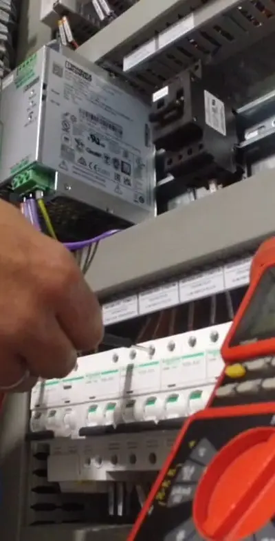
Control Panel Layout Optimisation
Control panel layout optimisation is the process of arranging components to make the most effective use of the available enclosure space without compromising safety, accessibility or reliability.
A panel that appears to fit on a drawing may still be difficult to manufacture, wire or maintain if the layout is not carefully considered.
Our layout optimisation process considers:
-
Logical grouping of components
-
Separation of power and control equipment
-
Cable-routing distances
-
Trunking capacity
-
Terminal accessibility
-
PLC and I/O access
-
Component clearances
-
Heat distribution
-
Door-mounted equipment
-
Cable-entry locations
-
Safe testing access
-
Future expansion space
-
Enclosure size
-
Ease of component replacement
The aim is not simply to make the panel smaller.
The aim is to create a practical arrangement that supports efficient manufacture, reliable operation and easier maintenance.
Separation of Power and Control Equipment
High-voltage power circuits, drives and contactors can generate heat and electrical interference.
Sensitive PLC, communication and instrumentation equipment must therefore be positioned and wired appropriately.
Panel layout design may include separation between:
-
Mains power and low-voltage control circuits
-
Variable-speed drives and communication equipment
-
Motor cables and analogue signals
-
Safety circuits and standard control circuits
-
Incoming supplies and outgoing field wiring
-
Heat-producing devices and sensitive electronics
Appropriate segregation helps reduce interference, improve reliability and simplify fault finding.
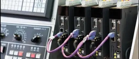
Thermal Calculations
Electrical components produce heat while operating.
If this heat cannot escape from the enclosure, the internal temperature may rise beyond the recommended operating limits of the installed equipment.
Thermal calculations help determine whether the proposed control panel can manage the expected heat load under normal operating conditions.
The calculation may consider:
-
Heat generated by electrical components
-
Enclosure dimensions
-
Enclosure material
-
Ambient temperature
-
Panel location
-
Internal component density
-
Variable-speed drives
-
Power supplies and transformers
-
Natural heat dissipation
-
Ventilation
-
Filters and fans
-
Air-conditioning or cooling units
-
Required internal temperature
Thermal assessment is particularly important for panels installed in hot production areas, confined plant rooms, outdoor locations or environments with high component densities.

Panel Cooling and Ventilation
Where natural heat dissipation is not sufficient, additional cooling may be required.
Depending on the environment and heat load, this may include:
-
Ventilation grilles
-
Filter fans
-
Extractor fans
-
Internal circulation fans
-
Air-to-air heat exchangers
-
Enclosure air-conditioning
-
Larger enclosures
-
Revised component positioning
-
Reduced component density
The cooling solution must also account for dust, moisture and the required enclosure protection rating.
A ventilation system that introduces contaminated air into the panel may create additional maintenance and reliability problems.
Cable Sizing
Correct cable sizing is essential for safe and reliable control panel operation.
Cables must be suitable for the current they will carry, the protection device being used and the conditions in which they are installed.
Cable sizing may consider:
-
Design current
-
Cable current-carrying capacity
-
Protective-device rating
-
Cable length
-
Voltage drop
-
Installation method
-
Ambient temperature
-
Grouping of cables
-
Conductor material
-
Insulation type
-
Fault current
-
Short-circuit withstand
-
Motor starting current
-
Variable-speed drive requirements
-
Customer and project standards
Incorrectly sized cables may overheat, create excessive voltage drop or fail to provide the required protection during a fault.
Power and Control Cable Selection
Different parts of the control panel require different cable types and conductor sizes.
This may include:
-
Incoming power cables
-
Motor cables
-
Internal panel wiring
-
Control wiring
-
Safety circuit wiring
-
Instrumentation cables
-
Analogue signal cables
-
Communication cables
-
Screened cables
-
Flexible conductors
-
Field multicore cables
The cable-selection process must also consider terminals, trunking capacity, bend radius and connection requirements.

Voltage-Drop Assessment
Voltage drop occurs as current travels through a cable.
Excessive voltage drop can prevent equipment from operating correctly, particularly where field devices are positioned a significant distance from the control panel.
Voltage-drop checks may be required for:
-
Motors
-
Solenoid valves
-
Contactors
-
Remote I/O
-
Sensors
-
Control-voltage circuits
-
DC-powered equipment
-
Long field-cable runs
Where necessary, cable sizes, power supplies or distribution arrangements can be adjusted during the design stage.
Designing for Maintenance and Fault Finding
Control panels must remain understandable and accessible after the original project has been completed.
Our control panel design process considers the engineers who will maintain the system throughout its operational life.
Maintainable panel design may include:
-
Clear wire numbering
-
Consistent component labels
-
Accessible terminals
-
Logical component grouping
-
Space for test equipment
-
Clear PLC and I/O identification
-
Structured electrical drawings
-
Spare terminals
-
Spare PLC capacity
-
Safe isolation arrangements
-
Accurate as-built documentation
These details can significantly reduce the time required to diagnose faults and complete future modifications.
Designing for Future Expansion
Industrial control systems often change as production requirements evolve.
Machines may be modified, new instruments may be added and additional equipment may need to be integrated.
Where appropriate, the panel design can include provision for:
-
Spare PLC I/O
-
Spare terminal capacity
-
Additional circuit protection
-
Extra cable-entry space
-
Larger power supplies
-
Network expansion
-
Additional trunking capacity
-
Physical component space
-
Future motor or drive circuits
Planning for realistic expansion during the original design can reduce the cost and disruption of later modifications.
Control Panel Design for Existing Systems
Stratos can also support businesses where the existing control panel documentation is incomplete, inaccurate or unavailable.
Our engineers can assess an existing system using:
-
Panel inspections
-
Electrical drawings
-
PLC hardware configurations
-
Existing PLC software
-
Terminal tracing
-
Equipment surveys
-
Original machine documentation
-
Operator and maintenance knowledge
This information can be used to update the drawings, identify risks and develop a design for refurbishment or replacement.
Integrated Electrical and Automation Design
The control panel should not be designed separately from the PLC software, machine operation or wider automation system.
Stratos combines control panel design with experience in:
-
Control panel manufacture
-
PLC programming
-
PLC upgrades and migration
-
Machine control
-
SCADA and HMI systems
-
Automation fault finding
-
Industrial communication networks
-
Testing and commissioning
This integrated approach helps maintain consistency between the electrical design, physical panel, PLC software and operational requirements.
Why Choose Stratos Control Systems?
Stratos provides practical industrial control panel design supported by automation and manufacturing experience.
Working with Stratos provides:
-
EPLAN and AutoCAD Electrical capability
-
Structured electrical schematics
-
Detailed I/O schedules
-
Practical panel layout optimisation
-
Thermal assessment
-
Cable-sizing calculations
-
PLC and automation expertise
-
Support for new and legacy systems
-
Design for manufacture
-
As-built documentation
-
UK-based engineering support
Our designs are created to support the full panel lifecycle, from initial concept through to manufacture, commissioning, maintenance and future upgrades.
Start Your Control Panel Design Project
Whether you need a new control panel, an upgrade to an existing system or accurate electrical documentation, Stratos Control Systems can help.
Speak to our engineers about a practical control panel design developed around your equipment, operational requirements and long-term support needs.
